Introduction⚓
An integrated circuit is designed from its description in terms of logical operators, taken from a library, linked by connections or equipotentials. This description is called the netlist. This netlist can be obtained either from a schematic or from a description in a high level language, for example VHDL. The role of an electronic circuit is to process electrical signals present on its inputs and to generate coherent signals on its outputs according to the specifications. The signal is the central object of the VHDL language:
- its declaration is infered in synthesis by an equipotential ;
- its state is defined by the assignment symbol (connection in the electronic sense)
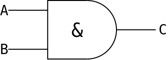
<=. e.g.:C <= A and B;(C receives A and B) will be synthesized by :
Good to know
VHDL is not case sensitive. But for better readability, be consistent.
Foreword⚓
The following pages give some examples of VHDL descriptions for elementary logic functions allowing logic synthesis. The proposed solutions are not exhaustive but they allow to ensure a correct electronic circuit for the synthesis. Before starting to write VHDL, you should :
- break down the circuit into a set of elementary blocks as simple as possible and have a complete and precise block diagram of the circuit with for each block the name of the inputs-outputs
- have a fairly precise idea of the nature of the operators that will be synthesized: combinatorial or synchronous with respect to a clock.
We will use standard packages that ensure the portability of VHDL from one tool to another such as numeric_std.
FPGA design flow⚓
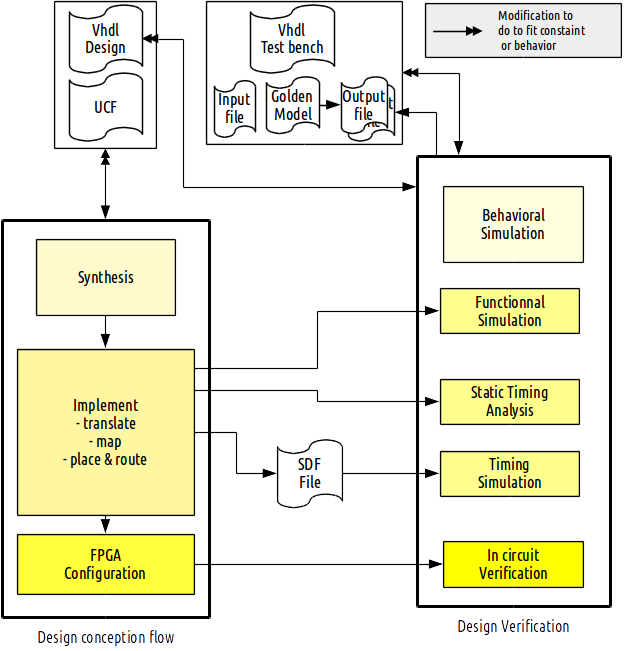
The design of a circuit, and its sub-modules, generally follows the following procedure when targeting a FPGA :
- Description of a golden model (non-synthesizable VHDL, C, Python, Matlab) for reference ;
- Design of a schematic architecture ;
- Description of this architecture in synthesizable VHDL ;
- Writing a test procedure (test bench with eventually input/output files, automation script...) ;
- Behavioral simulation ;
- If the behavioral simulation is successful, we proceed to the synthesis ;
- Post-synthesis simulation ;
- If the post-synthesis simulation is successful, we proceed to the implementation (translate, map, place and route) ;
- Post place and route simulation ;
- If the post place and route simulation is successful, we proceed to the FPGA ;
- Verification of the correct operation of the design on FPGA.
If one of the stage returns bad results, it is usually necessary to make changes in the VHDL description of the circuit.